


We continue the previous chapter by improving the robot description with Xacro and adding more properties to be able to simulate the robot in Gazebo. The code seems lengthy (since XML always requires opening and closing tags) but it is very simple to understand.
Xacro
In the last chapter, we created a URDF to describe all the links and joints of a mobile robot. However, you may notice several redundancies in this URDF, for example, the 4 wheels have almost identical components (except for the name, position, and orientation). For a more complex robot, there will be many more repeated components making the URDF both cumbersome and difficult to maintain. That's why Xacro was introduced. Xacro stands for XML Macro which allows you to use macros in a URDF to increase modularity and reduce redundancy. Note that Xacro is not an alternative to URDF but just another way of writing it because in the end a Xacro will be converted to URDF (automatically) while being loaded.
To understand Xacro syntax, let's create a new robot description file in urdf folder and name it mobile_robot.urdf.xacro. The full file is located here and below is the explanation for the main parts. The first two lines are similar to the mobile_robot.urdf, except in the robot tag, there is the line xmlns:xacro="http://www.ros.org/wiki/xacro" which basically defines XML namespace for the file to parse properly.
<?xml version="1.0"?>
<robot xmlns:xacro="http://www.ros.org/wiki/xacro" name="mobile_robot">
There are three shortcuts we can use with Xacro: property, math, and macro.
Xacro Property
In xacro, you can define a constant as a property and reuse it when needed. For example, in the snippet below three properties with names: height, width, and depth are defined with values 0.4, 0.4, and 0.1 (meter) respectively. They are then used in both visual and collision tags in the chassis link. The way you use a property is simply by putting it in dollar and curly bracket, for instance, <box size="${height} ${width} ${depth}"/>. The collision and inertial parts will be explained later in this post.
<xacro:property name="height" value="0.4" /> <!-- [m] -->
<xacro:property name="width" value="0.4" /> <!-- [m] -->
<xacro:property name="depth" value="0.1" /> <!-- [m] -->

<!--Chassis-->
<link name="chassis">
  <visual>
    <geometry>
      <box size="${height} ${width} ${depth}"/>
    </geometry>
  </visual>
  <collision>
    <geometry>
      <box size="${height} ${width} ${depth}"/>
    </geometry>
  </collision>
  <inertial>
    <mass value="1.0"/> <!-- [kg] -->
    <inertia ixx="0.014167" ixy="0.0" ixz="0.0" iyy="0.026667" iyz="0.0" izz="0.014167"/>
  </inertial>
</link>
Xacro Macro & Math
Now comes the wheels. Remember we have 4 separate descriptions for 4 wheels in the URDF from the last chapter? Here we can simply use a macro to describe a general wheel only once and use the parameters to define each wheel later in one line. You can think of writing a macro as creating a function with arguments.
<xacro:property name="wheel_height" value="0.04" /> <!-- [m] -->
<xacro:property name="wheel_radius" value="0.06" /> <!-- [m] -->

<!-- Wheel macro-->
<xacro:macro name="wheel" params="name reflect_x reflect_y reflect_r reflect_axis">

  <!-- Wheel link -->
  <link name="${name}_wheel">
    <visual>
      <geometry>
        <cylinder length="${wheel_height}" radius="${wheel_radius}"/>
      </geometry>
      <material name="blue"/>
    </visual>
    <collision>
      <geometry>
        <cylinder length="${wheel_height}" radius="${wheel_radius}"/>
      </geometry>
    </collision>
    <inertial>
      <mass value="0.3"/>  <!-- [kg] -->
      <inertia ixx="0.00031" ixy="0.0" ixz="0.0" iyy="0.00031" iyz="0.0" izz="0.00054"/>
    </inertial>
  </link>

  <!-- Wheel joint -->
  <joint name="${name}_wheel_joint" type="continuous">
    <parent link="chassis"/>
    <child link="${name}_wheel"/>
    <origin xyz="${reflect_x*height/2} ${reflect_y*(width/2+0.025)} 0" rpy="${reflect_r*1.5707} 0 0"/>
    <axis xyz="0 0 ${reflect_axis}"/>
  </joint>
</xacro:macro>
In the code above, the wheel macro is defined with 5 arguments: name, reflect_x, reflect_y, reflect_r, and reflect_axis. name is used for the link and joint names. reflect_x, reflect_y, reflect_r, and reflect_axis are used for the position of the joints. In the joint definition, it is shown how basic math operations can also be used in a xacro, e.g. <origin xyz="${reflect_x*height/2} ${reflect_y*(width/2+0.025)} 0" rpy="${reflect_r*1.5707} 0 0"/>.
Using this wheel macro, for example, the definition of the front right wheel looks like below. You can check if this description matches the old URDF by replacing the corresponding arguments in the xacro above with the values. Also, you should try to make the three remaining wheels by yourself.
<xacro:wheel name="front_right" reflect_x="1" reflect_y="-1" reflect_r="1" reflect_axis="-1"/>
Collision and Physical Properties
All the works we have done so far are for describing the visual characteristics of the robot meaning how it looks like. However, to enable collision detection and to simulate the robot in Gazebo more realistically, we need to add collision and physical properties.
Collision
You may already see the collision tags in the chassis and wheel links. The properties of collision are (quoted directly from the ROS wiki):
The collision element is a direct subelement of the link object, at the same level as the visual tag.
The collision element defines its shape the same way the visual element does, with a geometry tag. The format for the geometry tag is exactly the same here as with the visual.
You can also specify an origin in the same way as a subelement of the collision tag (as with the visual).
You may already notice that the collisions have exactly the same geometry as the links. This is true in many cases but if your robot has more complicated meshes or if you want to enlarge the geometry to ensure safety, then the collisions must be adjusted accordingly.
Physical Properties
In a simulated platform like Gazebo, there is a physics engine that emulates real-world physical properties such as gravity, friction, stiffness, etc. Therefore, we also need to add several important properties to our URDF. One of them is inertia. Every link element being simulated needs an inertial tag which you already can see in the chassis and wheel links above. It is a subelement of a link tag and gives two types of information: mass (in kilogram) and moments of inertia. For those of you who do not know "Moment of inertia, denoted by I, measures the extent to which an object resists rotational acceleration about a particular axis, it is the rotational analogue to mass (which determines an object's resistance to linear acceleration). The moments of inertia of a mass have units of dimension ML2([mass] × [length]2)" (source).
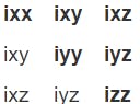
The inertia element is specified by a 3x3 matrix but can be represented by 6 elements since the matrix is symmetrical.
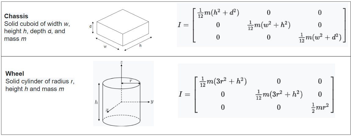
For simple shapes (box, cylinder, sphere) like in our mobile robot, the inertia matrix can be calculated using the formulas from this list of moment of inertia tensors. In the table below, you can calculate the inertia matrix by replacing the parameters in the formulas with values in the description code above. For more complicated meshes, this information can be extracted directly from 3D software such as MeshLab.
There are more physical properties such as friction, stiffness, and damping that you can add (more detail here). However, as we are only working with the simulation in Gazebo, we can use the gazebo tag to do it. For simplicity, I just use the material color Blue here, but you can add more properties (listed here) to make the simulation even more realistic.
  <gazebo reference="${name}_wheel">
    <material>Gazebo/Blue</material>
  </gazebo>
Launch and Drive the Robot
To drive our mobile robot in Gazebo, there are two more things you need to add to the Xacro file. First, every actuating joint, which is all the wheel joints in our case, requires a <transmission> block like below (since this is inside the wheel macro, the name argument is used).
  <!-- Adding transmission to wheels -->
  <transmission name="${name}_wheel_trans">
    <type>transmission_interface/SimpleTransmission</type>
    <actuator name="${name}_wheel_motor">
      <mechanicalReduction>1</mechanicalReduction>
    </actuator>
    <joint name="${name}_wheel_joint">
      <hardwareInterface>hardware_interface/VelocityJointInterface</hardwareInterface>
    </joint>
  </transmission>
Second, the gazebo_ros_control plugin is added to parse the transmission tags and load the appropriate hardware interfaces and controller manager in Gazebo.
<!-- Link Gazebo and ROS -->
<gazebo>
  <plugin name="gazebo_ros_control" filename="libgazebo_ros_control.so">
    <robotNamespace>/</robotNamespace>
  </plugin>
</gazebo>
Launch File
The Xacro is now complete and in order to launch it, create another launch file called drive_robot.launch. The full file is located here and I already added as many comments as possible to explain the information inside this file but if you are still unclear about anything, just leave me a message.
One important note is that this drive_robot.launch loads 2 files (can be downloaded from here and put in a config folder):
diffdrive.yaml which includes the configurations of the diff_drive_controller (differential drive controller), one of many controllers ROS provides and it is specifically used to calculate left and right angular velocities for wheel robots (more details can be found here).
gazebo_ros_control_params.yaml includes the configurations of controllers in Gazebo.
Drive the Robot in Gazebo
Open 2 terminals. In the first one, launch the file drive_robot.launch:
roslaunch ros_mobile_robot drive_robot.launch
Wait a few seconds for Gazebo to be fully loaded.
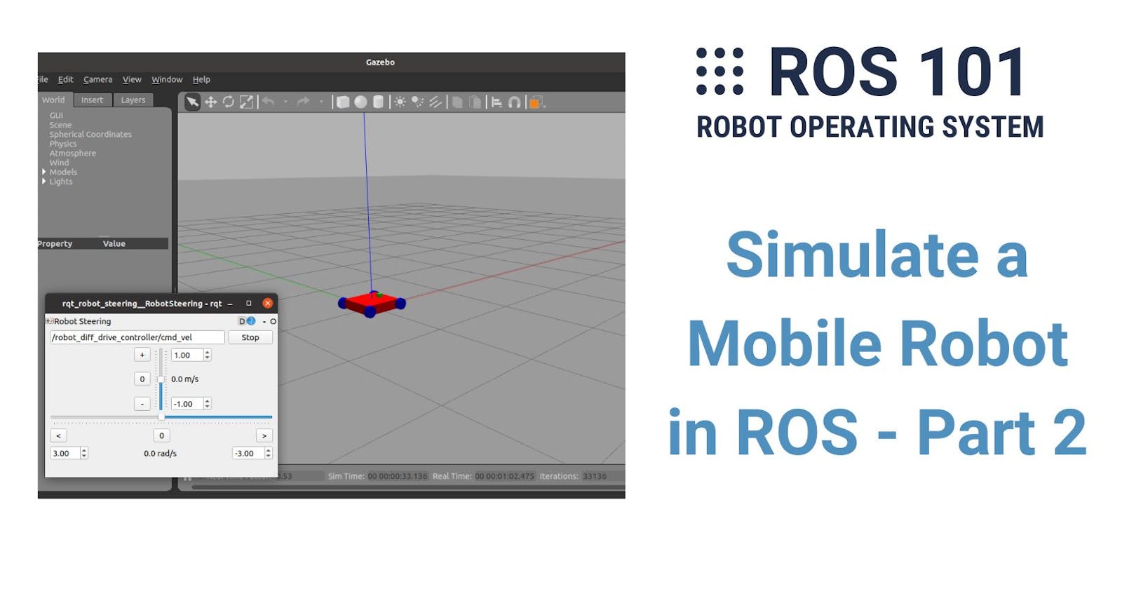
In the second terminal, run the rqt_robot_steering package which provides a GUI to steer robots. It basically lets you change the linear and angular velocities which are published to the topic /robot_diff_drive_controller/cmd_vel to drive the robot. If the topic name in the box is not /robot_diff_drive_controller/cmd_vel the same, manually edit it.
rosrun rqt_robot_steering rqt_robot_steering
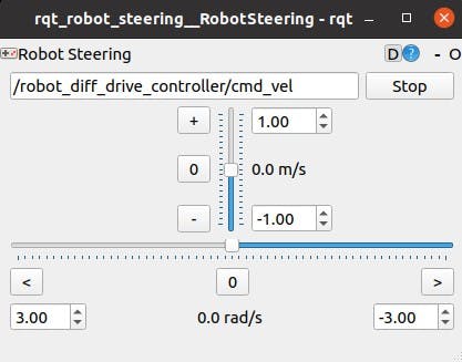
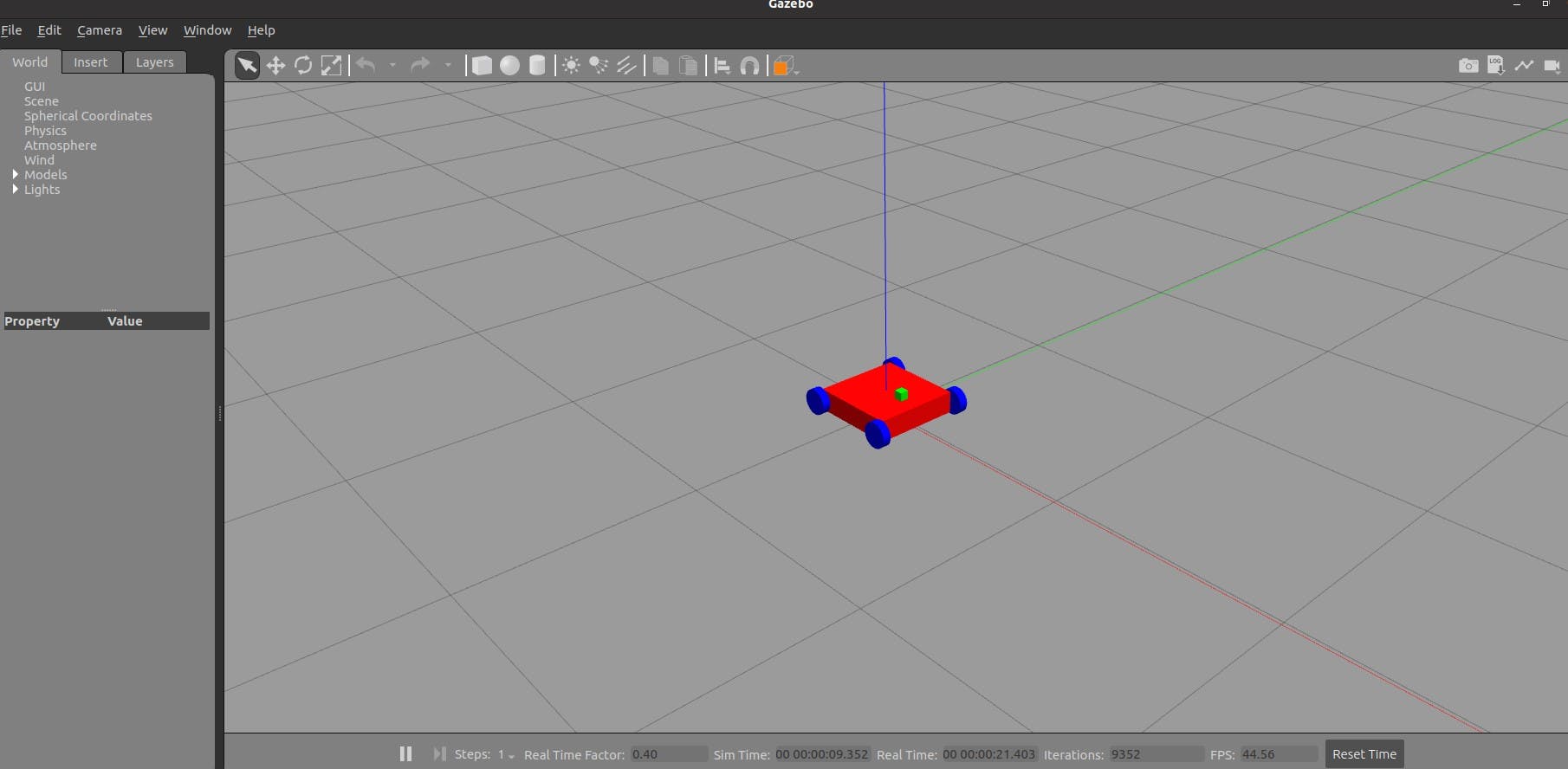
Change the linear and angular velocities in the GUI to steer the robot:
If you are using a virtual machine, you may notice that the simulation is not so responsive. It is because the simulation needs a lot of computation power. If you run this on a native Linux computer with a good graphics card, it should work better.
Is it exciting to see your robot moves? I bet it is. You have come a long way, very well done! The next chapter will be the last post of this series in which you will combine everything you have learned so far to control the robot with your hand gestures. See you there!