

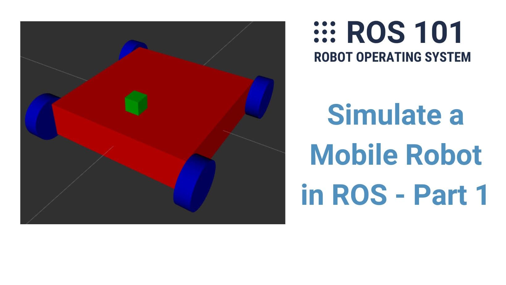
10. Simulate a Mobile Robot in ROS - Part 1
Search for a command to run...
File: setup.launch cua em de chay project
<launch>
<node pkg="minhtien" type="geostd.py" name="minhtien1"/>
<node pkg="teleop_twist_keyboard" type="teleop_twist_keyboard.py" name="minhtien2" output="screen"/>
<node pkg="rviz" type="rviz" name="minhtien3" args="-d $(find minhtien)/rviz/rviz.rviz" output="screen"/>
<node pkg="map_server" type="map_server" name="minhtien4" args="$(find minhtien)/map/mymap.yaml"/>
<node pkg="minhtien" type="initial.py" name="minhtien6"/>
<node pkg="minhtien" type="uart1.py" name="minhtien9"/>
<node pkg="minhtien" type="uart.py" name="minhtien7"/>
<node pkg="tf" type="static_transform_publisher" name="minhtien13" args="0 0 0 0 0 0 base_footprint laser 100"/>
<include file="$(find rplidar_ros)/launch/rplidar.launch"/>
<include file="$(find minhtien)/launch/move_base.launch"/>
<include file="$(find minhtien)/launch/amlc.launch"/> </launch>**
Em tich hop file cua a vao` project bang cach them dong code <include file="$(find minhtien)/launch/mobile_robot.launch/>
Error : Resource not found: ros_mobile_robot ROS path [0]=/opt/ros/noetic/share/ros ROS path [1]=/home/minhtien/Desktop/navigation/src ROS path [2]=/opt/ros/noetic/share The traceback for the exception was written to the log file
Em tích hợp file của a vào project thử thì có vấn đề ntn, em cần làm gì để cái file mobile_robot.launch tương thích với project của em ạ
Hi em,
Trong mobile_robot.launch của anh có dùng $(find ros_mobile_robot) để tìm package ros_mobile_robot. Nếu em để code vào package khác thì em phải sửa cho đúng tên.
Võ Minh Tiến Trong tab Global Options, phần Fixed Frame em chọn hoặc gõ base_link thay vì map. Trong hình ở bước 6 a có hướng dẫn đó.
As said in the previous post, I will not wait until the robot is complete and then make tutorials. This project log contains all the newest updates (ideas, changes, problems, etc.) that I encounter during this project from the start to the end. As al...
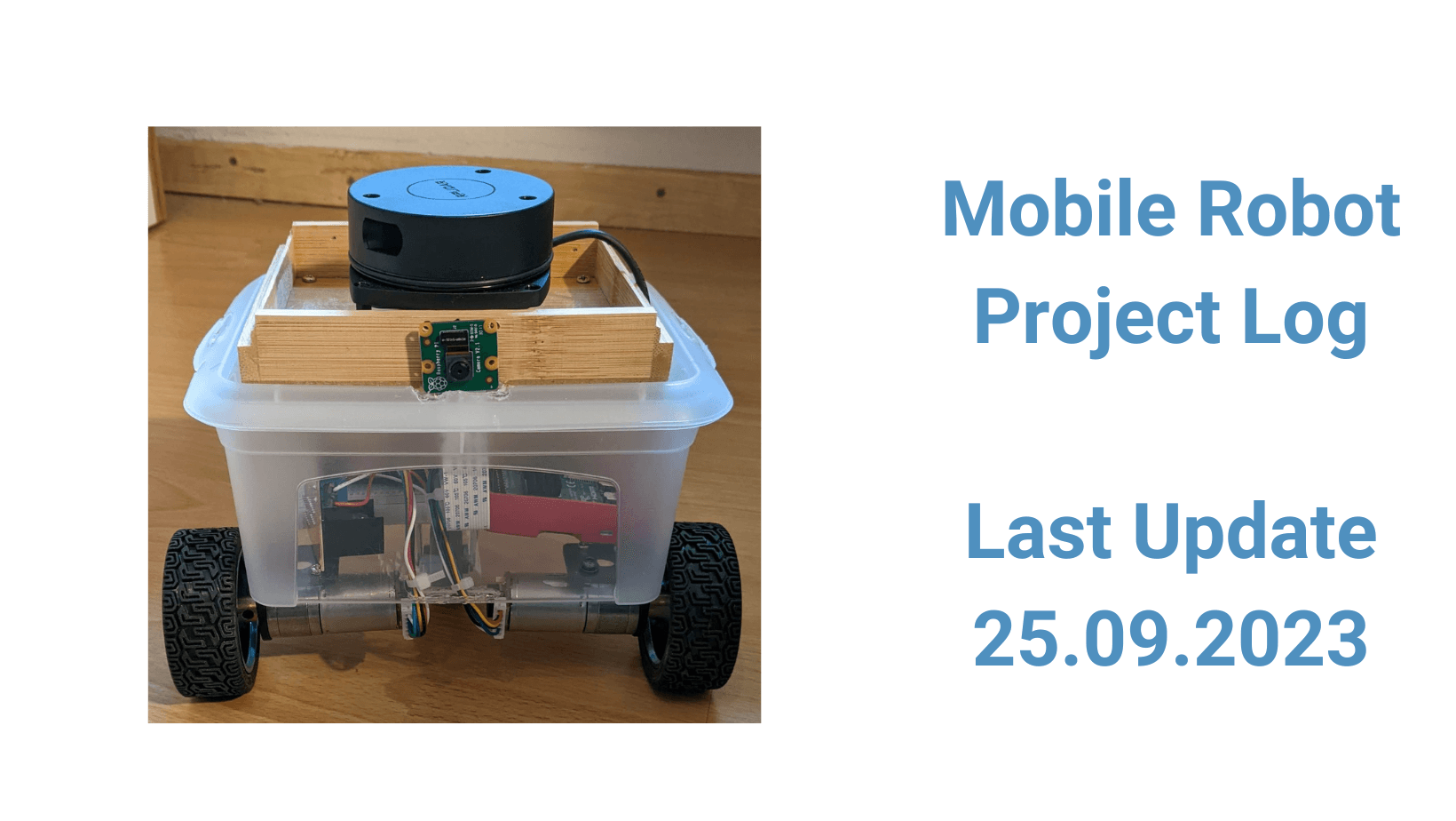
After the ROS 101 series, I am now planning to bring the mobile robot to life. Below are my rough idea and plan, but they will be updated regularly as the project grows. So stay tuned! The Idea The goal of this project is simple: to understand how al...

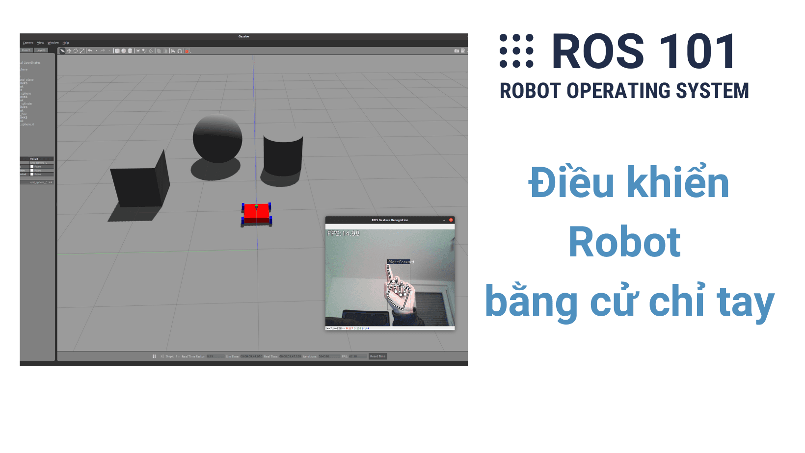
Trong chương cuối cùng của sê-ri ROS Cơ Bản này, chúng ta sẽ kết hợp mọi thứ đã học được cho đến nay để hoàn thành một nhiệm vụ cuối cùng: di chuyển robot bằng cử chỉ tay. Ý tưởng Ý tưởng để làm phần này thật ra rất đơn giản và cũng không có gì mới. ...
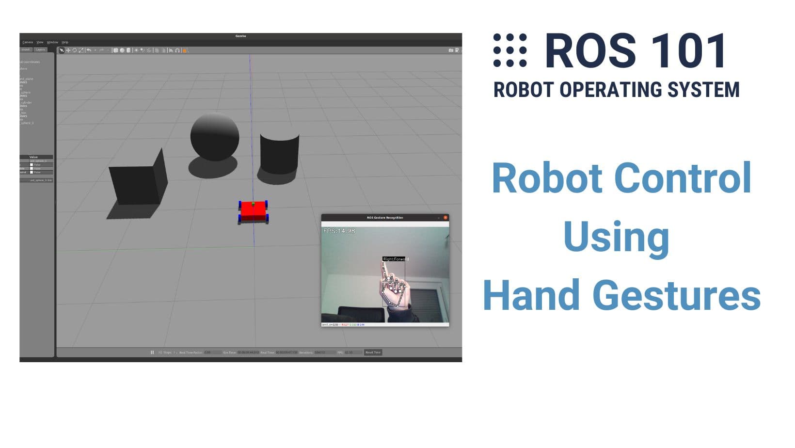
In this final chapter of the series ROS 101, we are going to combine everything we have learned so far to finish one last challenge: moving the robot with our hand signs. The idea The idea is pretty simple and there is actually nothing new. In the pr...
Hãy cùng tiếp tục chương trước bằng việc dùng Xacro để cải tiến mô tả robot (URDF) và thêm nhiều thuộc tính hơn để mô phỏng và điều khiển robot trong Gazebo. Code ở phần này nhìn có vẻ dài dòng (vì XML luôn yêu cầu các thẻ mở và đóng) nhưng thực ra r...
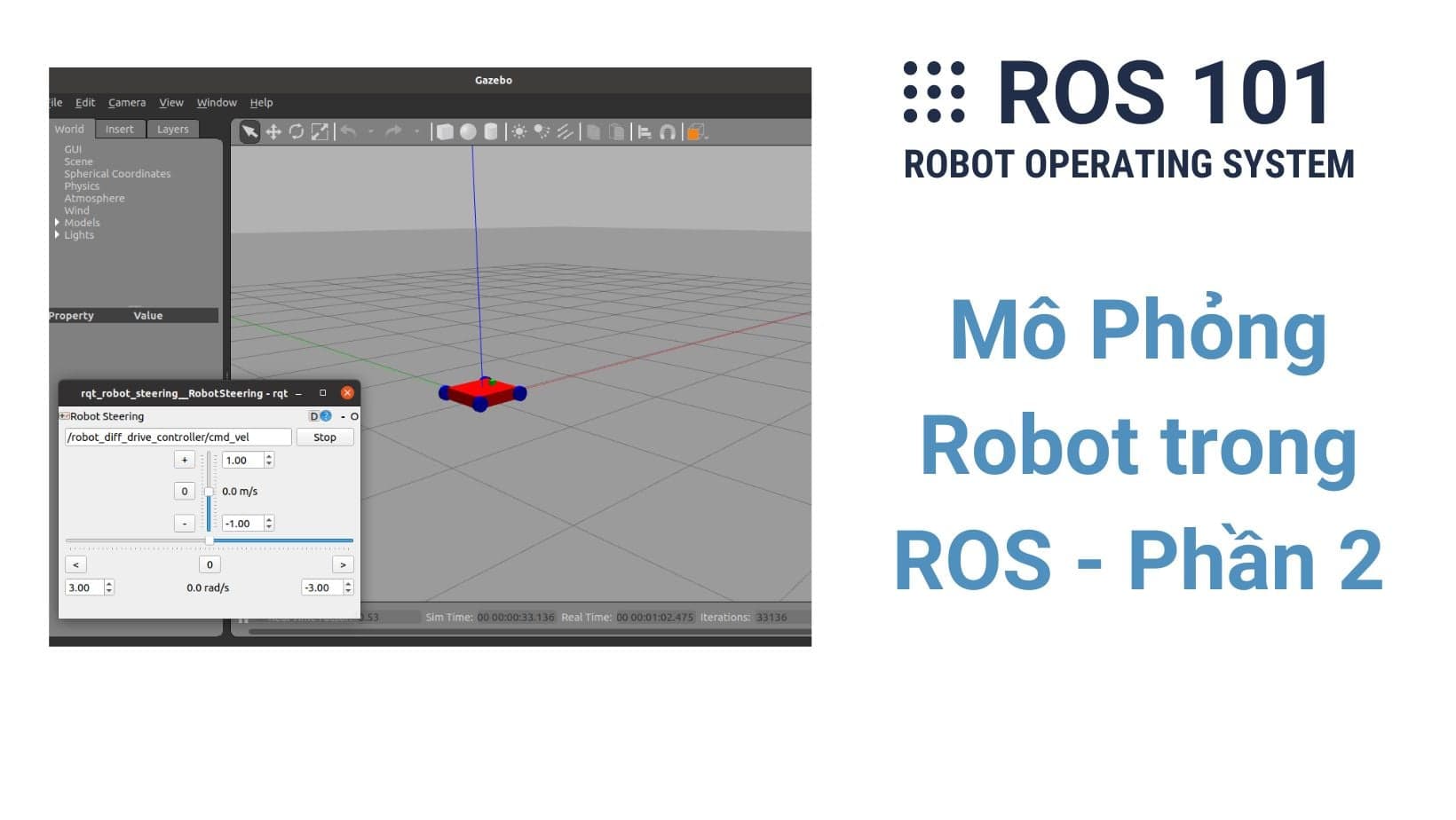
In this and the next chapter, you will learn to build a simulated robot and visualize its states with two programs coming with ROS: Gazebo and rviz. Gazebo is a 3D simulation platform, meaning it lets you model robots and environments that have physical properties such as gravity, speed, acceleration, etc., similar to the real world. When you do not have a real robot or you want to test your robot in a synthetic environment before trying it in real then you should use Gazebo. Rviz (short for ROS Visualization) is a 3D visualization software that helps monitor the robots' states such as sensor data (image, point cloud, trajectory, etc.), transformations between different coordinates, and so on. Rviz could be used for both simulated and real robots.
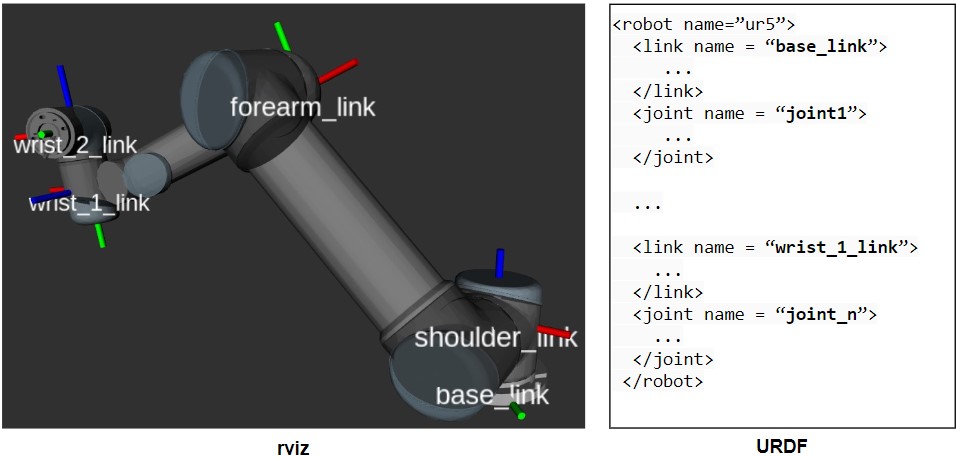
In order to visualize or simulate a robot in ROS, you need to describe it in a robot description file called URDF (Unified Robot Description Format). A URDF is basically an XML file that allows you to describe important physical properties of a robot such as links, joints, shapes, colors, collisions, etc. In the example below, on the left side you can see the visualization of a Universal Robot UR5 in rviz and the right side shows its (incomplete) URDF in which all components (links and joints, see step 4) are defined using tags (similar to package.xml and launch file from previous chapters). The complete URDF version of the UR5 robot is of course much longer than the one I show below but this is just to let you see its format.
In this part, you will learn to create URDF for a simple mobile robot and view it in rviz (then later in Gazebo). Just as a reminder, at the end of this series, you can use your hand gesture to control this robot. Cool, huh? I try to keep it as simple as possible and as always encourage you to read the instruction and type by yourself instead of copy/paste. The original package is located here.
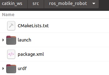
Create a new ROS package and name it ros_mobile_robot. Then build the workspace as well.
 cd ~/catkin_ws/src/
 catkin_create_pkg ros_mobile_robot
 cd ..
 catkin build
In the new package folder, make 2 new folders named: urdf and launch.
In the folder launch, create a launch file with the name mobile_robot.launch which you will use to call rviz to visualize the robot description you are going to write. The content of the launch file:
 <?xml version="1.0"?>
 <launch>
   <arg name="config" default="urdf"/>
   <param name="robot_description" textfile="$(find ros_mobile_robot)/urdf/mobile_robot.urdf" />
   <node name="joint_state_publisher" pkg="joint_state_publisher" type="joint_state_publisher" />
   <node name="robot_state_publisher" pkg="robot_state_publisher" type="robot_state_publisher" />
   <node name="rviz" pkg="rviz" type="rviz" required="true" args="-d $(find ros_mobile_robot)/urdf/$(arg config).rviz"/>
 </launch>
Explain: The first line <?xml version="1.0"?> is an XML declaration which is an optional indication of the version of XML. Inside the launch tag, an argument name config is defined with the default value as a string"urdf". Then, a parameter robot_description is created and textfile="$(find ros_mobile_robot)/urdf/mobile_robot.urdf" is simply the path to the URDF from step 5. Next, two nodes joint_state_publisher and robot_state_publisher are called to keep track of robot states such as the position & velocity of each joint and transformation between links. Finally, the rviz is called by launching the rviz package. If there is a .rviz file (which contains all the settings of rviz) existed in $(find ros_mobile_robot)/urdf/$(arg config).rviz, it will be loaded (otherwise, the default settings of rviz are launched). Since the argument config is by default urdf, this $(arg config).rviz equals to urdf.rviz. To get this urdf.rviz, see step 6.
In the folder urdf, create a file named mobile_robot.urdf and add the following lines
 <?xml version="1.0"?>
 <robot name="my_robot">

  <!--  All links and joints are declared here -->

 </robot>
A URDF always starts and closes with the robot tag. From now on, we will write all the descriptions of links and joints between <robot name="my_robot"> and </robot>.
But what are links and joints? Links are the rigid pieces of a robot (like bones in our body) and they are connected to each other by joints. Joints are parts of a robot that enable motions between connected links.
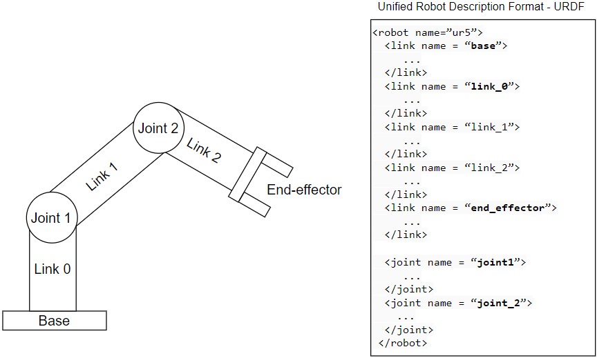
In the image above, the left side is a simple robot that has five links and two joints while the right side is its URDF. To concretely describe the links and joints, you need to fill in ... between their tags which you will learn in the next steps.
A link can be added using the <link> tag. It is standard in ROS to have a link as the origin of the whole robot. This is simply an empty link and I call it base_link here. Add these lines between <robot name="my_robot"> and </robot>.
   <link name="base_link">
   </link>
Next, define the chassis which is basically a box with dimensions (length x width x height) of 0.4 x 0.4 x 0.1 meters.
   <link name="chassis">
     <visual>
       <geometry>
         <box size="0.4 0.4 0.1"/>
       </geometry>
     </visual>
   </link>
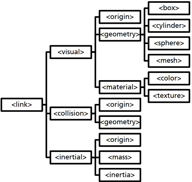
A <link> has three elements: <visual> for describing the visual properties (shape of the link), <collision> for describing collision volumes (to check if links collide), and <inertial> for defining the moment of inertia (a crucial physical property for realistic simulation, e.g. in Gazebo). The diagram below shows all the subcomponents of <link>. In the code above, only the <visual> and its child <geometry> (and its child <box>) is used to create a box with dimensions of 0.4 x 0.4 x 0.1 meters (length x width x height). The <collision> and <inertial> will be added later.
Next, we need to add a joint between base_link (parent link) and chassis (child link) which is a fixed joint because there is no movement here.
   <joint name="chassis_joint" type="fixed">
     <parent link="base_link"/>
     <child link="chassis"/>
   </joint>
To visualize what you just created, launch the mobile_robot.launch from step 3 by:
roslaunch ros_mobile_robot mobile_robot.launch
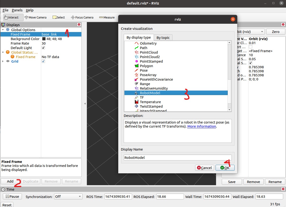
This opens rviz but there is nothing to see at the beginning. In order to view your robot model, follow these steps (see the photo below): First, change the Fixed Frame to base_link instead of map. Then, click Add button and select RobotModel in the list. Click OK and you should see a box in the middle of the grid. With your mouse, you can rotate (left-click), move X/Y (middle-click), and zoom (right-click or mouse wheel).
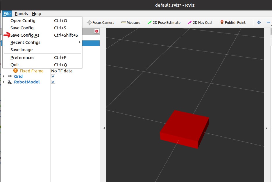
Save all the configurations you just edited in rviz to a file by going to File > Save Config As or using Ctrl+Shift+S. Then, save this as urdf.rviz in the folder ~/catkin_ws/src/ros_mobile_robot/urdf. The path to this urdf.rviz was already defined in the launch file from step 3 so the next time you launch it, you don't have to add the RobotModel, and change the Fixed Frame again.
The chassis is done! It's time to add wheels. Below is one example showing the descriptions of the right front wheel and its joint to the chassis look like.
   <material name="blue">
     <color rgba="0 0 0.8 1"/>
   </material>

   <!--right front wheel-->
   <link name="front_wheel_right">
     <visual>
       <geometry>
         <cylinder length="0.04" radius="0.06"/>
       </geometry>
       <material name="blue"/>
     </visual>
   </link>

   <joint name="front_wheel_right_joint" type="continuous">
     <parent link="chassis"/>
     <child link="front_wheel_right"/>
     <origin xyz="0.2 -0.225 0" rpy="1.5707 0 0"/>
     <axis xyz="0 0 -1"/>
   </joint>
Explain: First, a material tag with blue color is created (to paint the wheel later). The wheel link is pretty similar to the chassis with the geometry now a cylinder instead of a box. The cylinder has a length of 0.04 m and a radius of 0.06 m. The wheel has the color blue (to be easily distinguished from the chassis). The joint between the chassis (parent link) and the right front wheel (child link) is a continuous joint (i.e. a continuous hinge joint that rotates around the axis and has no upper and lower limits). More types of joints in URDF can be found here.

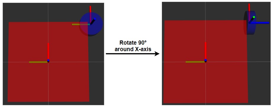
The <origin> is used to describe the position and orientation of the child link with respect to the parent link. In the image above, you can see that the wheel is 0.2 m in X, -0.225m in Y, and 0 m in Z. It also needs to rotate 90° (or 1.5707 radians) counter-clockwise along the X-axis of the chassis otherwise the Z-axis (in blue) of the wheel is pointing upward (see image below). If you want to visualize the axes, you should click on Add button and select TF (stands for transformation) which is right under the RobotModel in the dialog. Here, X is Red, Y is Green and Z is Blue (so XYZ <-> RGB).
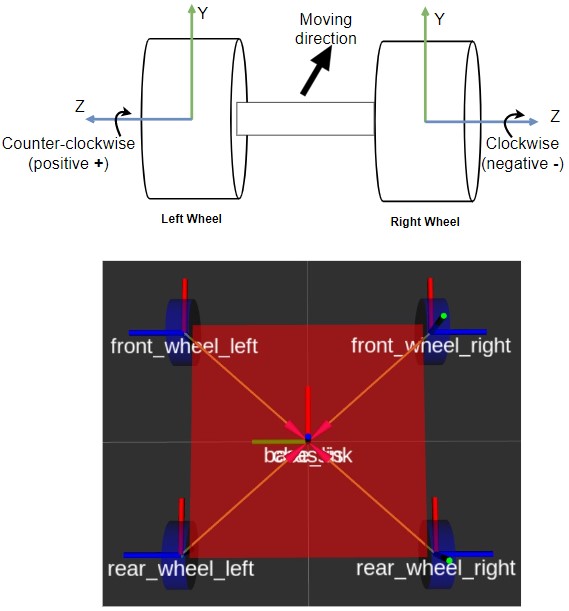
Finally, the <axis> tag defines the axis of rotation which is the Z-axis (of the wheel not the chassis) in this case. So it is set to xyz="0 0 -1" since there is only movement on Z-axis. You may wonder why -1 instead of 1. It is because the common convention for rotating direction is that clockwise is negative and counter-clockwise is positive. In this case, when I want the robot to move forward, the right wheels should move clockwise along its Z-axis meaning negative, hence -1. The left wheels, on the other hand, move counter-clockwise when the robot moves forward so they have positive Z or simply 1 (see image below).
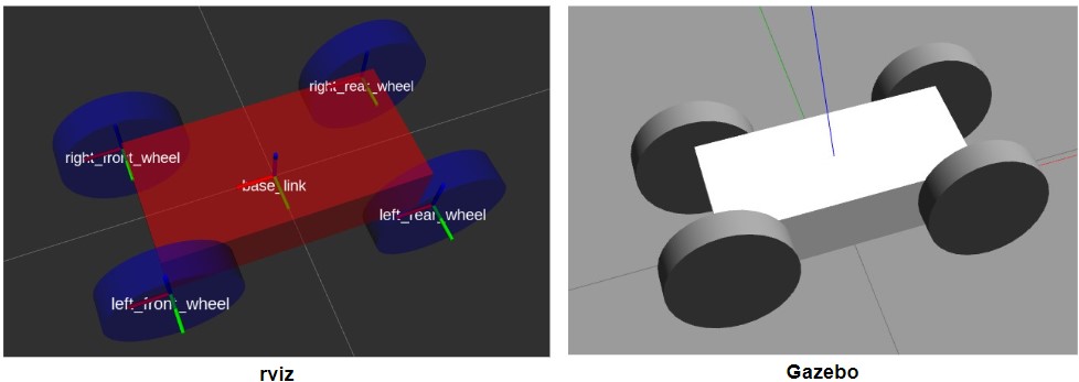
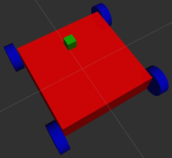
Try to follow the idea above and add the other 3 wheels by yourself. Another exercise for you is to add a small box on the top front of the robot so you know where its head is. You can refer to the source code here. After that, launch the mobile_robot.launch again and the final result should look like this:
And that's it! Now you know how to describe a robot by a URDF and visualize it in rviz. To make a robot look more professional like the UR5 above, you need to create a detailed mesh (CAD) file for each part which is of course not the purpose of this series. In the next chapter, I will show you how to add more properties to links and joints to be able to simulate (and move) the robot in Gazebo. Keep up the good work!